About Wedge Barriers

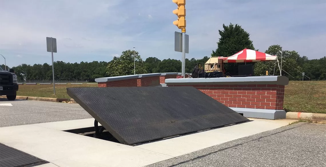
In the adhering to conversation, referral is made to a surface of a foundation to which the wedge-style obstacle is placed. In the detailed embodiments, the upper side of the support is substantially flush with the surface of the structure. In such embodiments, the wedge-style barrier may be placed straight to the surface area of the foundation. In other embodiments, the upper side of the anchor may be slightly raised over the surface of the foundation or somewhat recessed listed below the surface of the foundation. 1 is a front perspective view of a personification of a surface-mounted wedge-style barrier 10. As shown, the obstacle 10 is placed to a surface area 12 of a structure 14(e. g., a superficial structure ). For example, the structure
14 and the surface 12 to which the barrier 10 is safeguarded might be made from concrete - Wedge Barriers. 2, the obstacle 10 is mounted to or includes a support or subframe (e. g., anchor 30 received FIG. 2 )protected beneath the surface area 12. For instance, the bather 10 might be bolted to the support or safeguarded to the support by various other mechanical fasteners. In the illustrated embodiment, the obstacle 10 includes a wedge plate 16, that includes a part that is substantially identical with the surface 12 when the barrier 10 is in the retracted position. In other words, lorries or individuals may pass over the obstacle 10 when the barrier 10 is in the retracted position and experience small elevation about the surface area 12 while on the obstacle 10. As reviewed thoroughly listed below, when the barrier 10 is in the released setting, the wedge plate 16 is held and supported in an increased setting by a training system of the barrier 10. In addition, the elements 18 might be bolted or otherwise mechanically coupled to each other. In this fashion, repair work or replacement of several parts 18 might be simplified and structured. That is, repair work or substitute of single parts
18 may be done more quickly, conveniently, and price efficiently. FIG. In specific embodiments, the anchor 30 may be a steel frame including plates, beam of lights(e. g., I-beams ), and/or various other frameworks that are safeguarded within the structure 14, which might be concrete. At the surface 12, an upper side 28 of the support 30 may be at the very least partially subjected
, consequently enabling the add-on of the barrier 10 to the support 30. g., threaded holes)in several beam of lights or plates of the anchor 30 might be revealed to the surface 12. In this way, bolts 32 or various other mechanical fasteners might be made use of to protect the obstacle 10 to the anchor 30. As the obstacle 10 is placed to the surface area 12 of the foundation 14, collection of debris and other material under the barrier may be lowered, and parts of the bather 10 might not be revealed to below quality environments. As indicated by recommendation character 52, the lifting mechanism 50 includes components disposed under the wedge plate 16. The elements 52 below the wedge plate 16 might consist of an electromechanical actuator, a cam, one or more web cam surface this website areas, and so forth. Furthermore, the lifting device 50 includes a springtime setting up 54
The spring rod 58 is paired to a camera(e. g., webcam 80 displayed in FIG. 4) of the lifting device 50. The springs 60 disposed regarding the spring pole 58 are held in compression by spring sustains 62, consisting of a dealt with springtime support 64. That is, the set springtime assistance 64 is repaired about the structure 14 and the rest of the bather 10.
3 Easy Facts About Wedge Barriers Shown
The remaining force applied to
the cam webcam deploy release wedge plate 16 may might provided by an electromechanical actuator 84 or other actuator. The springtime assembly 54 and the actuator 84(e. Wedge Barriers. g., electromechanical actuator)may operate with each other to convert the webcam and raise the wedge plate 16.
As discussed over, the springtime setting up 54 exerts a consistent pressure on the web cam, while the electromechanical actuator may be controlled to put in a variable force on the web cam, thereby enabling the lifting and lowering( i. e., releasing and withdrawing )of the wedge plate 16. In certain personifications, the continuous pressure applied by the spring setting up 54 might be flexible. g., electromechanical actuator) is handicapped. As will be valued, the spring assembly 54 might be covered and safeguarded from debris or various other elements by a cover plate(e. g., cover plate 68 displayed in FIG. 4) that may be substantially flush with the elevated surface 38 of the structure 14. As mentioned above, in the deployed setting, the wedge plate 16 serves to block accessibility or travel beyond the barrier 10. The obstacle 10(e. g., the wedge plate 16 )might block pedestrians or vehicles from accessing a building or pathway. As reviewed over, the barrier navigate to these guys 10 is affixed to the support 30 safeguarded within the structure 14,
front braces 71. Therefore, the affiliation assemblies 72 may pivot and turn to allow the collapse and extension of the affiliation settings up 72 throughout retraction and release of the bather 10. The linkage assemblies 72 reason movement of the wedge plate 16 to be restricted. If an automobile is taking a trip towards the deployed wedge plate 16(e. For example, in one condition, the safety legs 86 may be expanded duringmaintenance of the barrier 10. When the safety legs 86 are deployed, the safety and security legs 86 support the weight of the wedge plate 16 versus the surface 12. Consequently, the training system 50 might be shut down, serviced, gotten rid of, changed, and so forth. FIG. 5 is partial perspective view of an embodiment of the surface-mounted wedge-style obstacle 10, illustrating the camera 80 and the camera surfaces 82 of the training system 50. Especially, two camera surface areas 82, which are described as reduced web cam surfaces 83, are placed listed below the web cam 80. The lower cam surfaces 83 might be taken care of to the surface 12 (e. As an example, the lower camera surface areas 83 and the mounting plate 85 may create a solitary item that is secured to the anchor 30 by screws or other mechanical bolts. Furthermore, 2 webcam surface areas 82, which are referred to as upper camera surfaces 87, are placed over the cam 80 and paired to (e. In other personifications, stepping in layers or plates might be placed between the surface 12 and the More Info reduced webcam surface areas 83 and/or the wedge plate 16 and the top cam surfaces 87 As mentioned over, the webcam
80 equates along the cam surfaces 82 when the wedge plate 16 is lifted from the retracted placement to the released position. Furthermore, as discussed above, the spring setting up 54 (see FIG. 3 )might provide a pressure acting on the webcam 80 in the direction 102 using springtime rod 58, which might lower the force the electromechanical actuator 84 is needed to put on the camera 80 in order to actuate and lift the wedge plate 16. 1 )to the released position(see FIG. 4). As revealed, the camera 80 includes track wheels 104(e. g., rollers), which call and convert along the camera surface areas 82 during procedure.